Previous Section

IV. APPENDIX

A. DESIGNER'S CHECKLIST

Below is a summary of hardware design considerations and precautions:

POWER:

  1. Supply a transient-free +5V- this supply should power all components which drive the data control bus.
  2. Provide the specified "VDD-VO" voltage to the module's contrast pin (VO). Do not connect a capacitor between this point and ground, VO must never exceed VDD.
  3. This VDD-VO spec may exceed 5V, on some models, indicating that a negative supply is required. The negative source is connected to one end of the VO control potentiometer.
  4. Never insert or remove a module from a live circuit.

HARDWARE:

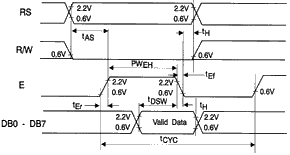
  1. Develop a uniquely decoded "E" strobe puse, active high, to accompany each module transaction.
  2. This "E" strobe must be at least 450 nS wide.
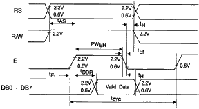
  3. Module inputs RS and R/W "set-up" 140 nS prior to the rise of "E".
  4. Data sets-up 195 nS prior to the fall of "E".
  5. RS, R/W, and data all "hold" 10 nS after the fall of "E".
  6. Assign the display a "global" address which generates a uniquely decoded output.
  7. Assign 1 or 2 additional bits, whether address or control, to drive the RS and R/W inputs. (R/W may be grounded for write-only applications.
  8. Observe the module's "execution-time". (See software section). The module "goes-busy" for some 40 to 1600 microseconds after a transaction. Transfers during this "busy" period will not be accepted.
  9. Utilize the host's extended timing mode, if available, when transacting with the LCD. Use those instructions which prolong the RD and WR, or other appropriate data strobes.
  10. If a parallel port is used to drive the RS, R/W and "E" control lines, be certain not to set the "E" control lines, be certain not to set the "E" bit simultaneously with RS and R/W. This violates the moduel's set-up time. A separate instruction must be employed.

MOUNTING

  1. Install so that the module is warp free and no pressure is applied to the bezel.
  2. Protect the display surface from contamination and foreign objects.

B. PRECAUTIONS IN HANDLING AND OPERATING LCD MODULES

These precautions apply equally to modules from all makers - not just Densitron. When these rules are followed an extraordinary service life can be achieved. Violation of these guidelines can cause problems ranging from erratic operation to catastrophic display failure.

POWER SUPPLY PRECAUTIONS:

  1. Identify and, at all times, observe absolute maximum ratings for both logic and LC driver. Note that there is some variance between models. Check yours!
  2. Prevent the application of reverse polarity, however, briefly.
  3. Use a clean power source free from transients. Power up conditions are occasionally "jolting".
  4. The +5V power for the module should also supply the power to all devices which may access the display. Don't allow the data bus to be driven when the logic supply is disabled.
  5. Do NOT install a capacitor between the VO (contrast) pin and ground. VDD must, at all times, exceed the VO voltage level. The capacitor combines with the contrast potentiometer to form an R-C network which "holds-up" VO, at the power-down, damaging the module.

OPERATING PRECAUTIONS:

  1. Do NOT plug or unplug the module which the system is live.
  2. Minimize the cable run between the module and host. Long lengths may introduce noise or damaging voltages due to antenna-effect.
  3. Don't disable the EL backlight by interrupting the AC line. Unloaded inverters produce voltage extremes which may arc within a cable or at the display.

MECHANICAL/ENVIRONMENTAL PRECAUTIONS:

  1. Improper soldering is the major cause of module difficulty, Water based solders are not recommended. We recommend Kester"44" resin solder. The flux is non-corrosive and electrically non-conductive. The flux residues do not need to be cleaned off.
  2. Mount the module so that it is free from torque and physical loads.
  3. The display font is an easily scratched, plastic polarizer. Avoid contact and clean only when necessary with soft, absorbent cotton dampened with petroleum benzine.
  4. Employ anti-static procedures, always, while handling the module. Use a lear protection plate between the module and the outside world.
  5. Prevent moisture build-up upon the module.

C. TROUBLESHOOTING GUIDE

Sympton:
A) No display after initialization and data sent.
Probable cause:

  1. VO voltage not properly set. Check specification. Some displays require a negative voltage at this pin. Set up VO with potentiometer that will adjust over full range from VDD to VSS, or VDD to VEE (-5VDC). (See Power Supply Section).
  2. Timing violated. Check that all set up times are followed. check that Enable pulse must be 450nS minimum.
  3. Execution times violated. Do not send signals for 15mS after power up. Allow 1.6mS after Clear and Return Home Instructions are sent; 40mS after other instructions and the data are sent.
  4. Improper initialization. It's always a good idea to send an initialization routine after power up. The internal routine leaves the display in the OFF condition.
  5. Do not store in direct sunlight.
  6. If leakage of the liquid crystal material should occur, all contact with this material, particularly ingestion, must be avoided. If skin or clothing becomes contaminated, wash thoroughly with soap and water.
  7. Display misconnected. Check all connections. Ensure no I/O pads are bridged.
  8. Signal levels incorrect. Insure data bus components have CMOS or TTL level outputs. Measure 2.4VDC min. for logic high and I/O connections on display.
  9. Power supply out of tolerance or "dirty". Check +5VDC and ground.

B) Displays randomly or unreliably.
Probable cause:
Check b), c). d), e), & g) above.

C) Only 1 line will display on a 2 line module.
Probable cause:
Display initialized as 1 line display. Send proper initialization codes.

C) Missing rows or columns of dots
Probable cause:
Display has been mounted so that torque or pressure is applied to PPC and/or bexel. Unmount and recheck.


D. TIMING DIAGRAMS


Write Operation

ITEM SYM MIN MAX UNIT
Enable Cycle Time tcycE 1000   nS
Enable Pulse Width PW EH 450   nS
Enable Rise/Fall Time tEr, tEf   25 nS
Address Set-up Time tAS 140   nS
Address Hold Time tAH 10   nS
Data Start-up Time tDSW 195   nS
Data Hold Time tDHR 10   nS


Read Operation

ITEM SYM MIN MAX UNIT
Enable Cycle Time tcyc E 1000   nS
Enable Pulse Width PW E 450   nS
Enable Rise/Fall Time tEr, tEf   25 nS
Address Set-up Time tAS 140   nS
Address Hold Time tAH 10   nS
Data Delay Time tDSW   320 nS
Data Hold Time tDHR 10   nS

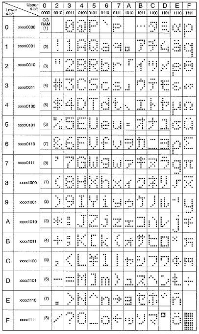
E. FONT CHART


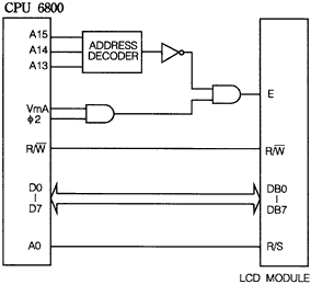
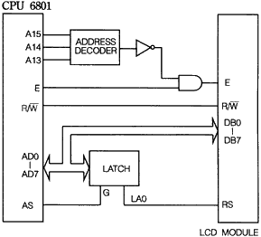
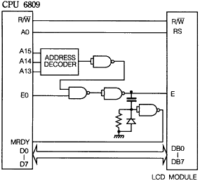
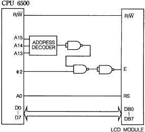
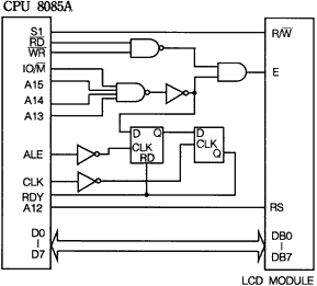
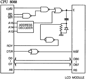
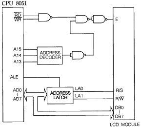
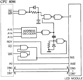
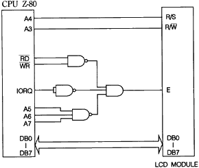
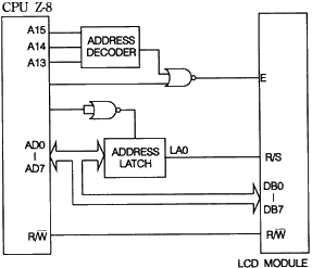
F. PROCESSOR SPECIFIC INTERFACE SUGGESTIONS


G. DESCRIPTION OF POLARIZER TYPES for LIQUID CRYSTAL DISPLAYS

TYPE P/N CODE DESCRIPTION DIRECT SUNLIGHT OFFICE LIGHT SUBDUED LIGHT VERY LOW LIGHT COMMENTS
Reflective Positive A Dark Characters on a Light Gray or Yellow Background Excellent Very Good Poor Unusable Cannot be backlit
Transflective Positive B Dark Characters on a Light Gray or Yellow Background Excellent (Lamp Off) Very Good (Lamp On) Very Good (Lamp On) Very Good (Lamp On) Best Choice for all around use
Transmissive Negative E Lighted Characters on a Dark Background Poor (Lamp On) Good (Lamp On) Very Good (Lamp On) Excellent (Lamp On) Backlight must always be on
Transmissive Positive * F Dark Characters on a Light Gray or Yellow Background Good (Lamp Off) Very Good (Lamp On) Excellent (Lamp On) Excellent (Lamp On) Lighted background is brighter than "B" type

* Limited Availability